
What Are You Looking For?
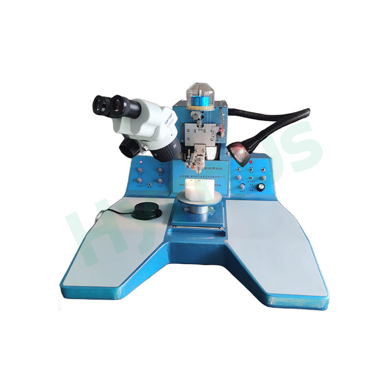

HY-PM252-6R Molding is a high-precision molding mold designed for TO252-6R package products. The mold features a universal mold base capable of accommodating 6 mold boxes with quick mold box change design, utilizing a bottom-to-top multi-pot injection design driven by four built-in high-temperature-resistant, leak-proof hydraulic cylinders with a balanced injection head drive plate.
Brand :
HYRNUSItem No. :
HY-PM252-6ROrder(MOQ) :
1 SetWarranty :
One-Year Warranty and Lifetime MaintenancePayment :
T/TLead Time :
7-35 DaysProduct Origin :
ChinaHigh-Precision Molding Mold for TO252-6R

Product Introduction
HY-PM252-6R Encapsulation Mold are fully interchangeable on the mold base without position-specific identification. Key materials include DC53 mold boxes (hardness HRC59–60), ASP23 cavities, inserts, and center blocks (hardness HRC61–63), ASP23 injection barrels, and tungsten carbide injection heads. The leadframe loading plate is made of high-strength aluminum alloy with a floating support design. The mold accepts a maximum of 100,000 shots or 1 year of use, with acceptance standards covering external dimensions (L×W×T), roughness, draft angles, and cavity surface quality. Quality requirements include misalignment ≤0.05mm in any direction, flash control with no impact on downstream automatic handling, mold compound leads with flash controlled within 1.0mm, and void/pinhole size <0.1mm on mold compound surface. Internal defects such as voids above chip/lead bond areas are not allowed, while voids elsewhere must be ≤0.1mm. The mold operates at 160–180°C mold temperature with injection pressure of 1000–1600 psi and injection time of 8–25 seconds. The cavity coating supports 150k shots (green pellet) or 200k shots (standard pellet) without peeling.
Quality Requirements for Molded Products
| Item | Acceptance Standard | Standard after 100,000 shots or 1 year |
| External dimensions: L × W × T | Per molded product drawing | - |
| Top length, top width, top thickness | Per molded product drawing | - |
| Bottom length, bottom width, bottom thickness | Per molded product drawing | - |
| Lead thickness | Per molded product drawing | - |
| External features | ||
| Roughness Ra | Per molded product drawing | - |
| Top draft angle | Per molded product drawing | - |
| Bottom draft angle | Per molded product drawing | - |
| Cavity | Chrome-plated surface | - |
| Misalignment (X, Y direction) | ||
| Any direction offset of top/bottom mold compound | ≤0.05 | - |
| Any direction offset between mold compound center and leadframe center | ≤0.05 | - |
| Flash at one end of runner/vent groove | No impact on automatic handling in downstream processes | No impact on automatic handling in downstream processes |
| Residual film-like flash thickness at vent end of mold compound | No impact on automatic handling in downstream processes | No impact on automatic handling in downstream processes |
| Residual waste material at gate end after separation, extending outward from root | No impact on automatic handling in downstream processes | No impact on automatic handling in downstream processes |
| Upward protrusion of residual waste material at gate end after separation, starting from the dam bar | None | None |
| Mold compound leads | No flash allowed on lead surface; if transparent flash exists, it must be controlled within 1.0 mm | - |
| Mold release performance | Good mold release; no breakage of ejected runner or cull | Good mold release; no breakage of ejected runner or cull |
| Molding parameters (during acceptance) | ||
| Mold temperature | 160–180°C | - |
| Injection pressure on material | 1000–1600 psi | - |
| Injection time | 8–25 sec | - |
| Surface defects | ||
| Cavity scratches/marks (as seen on product surface) | None | - |
| Wavy marks on cavity surface (as seen on product surface) | None | - |
| Void size on mold compound surface | <0.1 | - |
| Pinhole size on mold compound surface | <0.1 | - |
| Cracks or chipping on mold compound surface | None | - |
| Chimney-like flash thickness/height on top edge of ejector pin | None | - |
| Vertical thin-edge flash thickness/height at insert joint surface | ≤0.05 | ≤0.05 |
| Center residual pellet flash overflow thickness/width | ≤0.05 | <0.05, <2 |
| Flash overflow thickness/width on both sides of runner | ≤0.05 | <0.05, <1 |
| Leadframe deformation or pilot hole tear after mold opening/ejection | Not allowed | Not allowed |
| Internal defects | ||
| Void size above chip/lead bond area and below paddle | None | - |
| Number of voids above chip/lead bond area and below paddle | None | - |
| Delamination size above chip/lead bond area and below paddle | Not allowed | - |
| Void size elsewhere in mold compound | ≤0.1 mm | - |
| Non-fill | Not allowed | - |
| Cavity coating | 150k shots (green pellet), 200k shots (standard pellet); no coating peeling (shot count preferred) | - |
Mold Configuration
| Item | Standard |
| Mold Body | The mold must be compatible for use on the buyer's press of 550 tons or above. |
| Universal mold base capable of accommodating 6 mold boxes, with quick mold box change design. | |
| Injection type: bottom-to-top multi-pot injection design. Injection action is driven by four built-in high-temperature-resistant, leak-proof hydraulic cylinders, with a balanced injection head drive plate. | |
| Each mold box is fully interchangeable on the mold base without the need to identify specific positions. | |
| Components within each mold box are fully interchangeable; various inserts can be mutually replaced. | |
| Mold box design includes a built-in ejector pin plate mechanical structure connected to the ejector drive device inside the mold base, as well as rail-type extraction and insertion design for quick mold box change. | |
| Mold box and its main components shall be made of materials meeting or exceeding the following requirements: | |
| - Mold box: DC53 (hardness: HRC59–60) | |
| - Cavities and inserts: ASP23 (hardness: HRC61–63) | |
| - Center block: ASP23 (hardness: HRC61–63) | |
| - Injection barrel: ASP23 | |
| - Injection head: Tungsten carbide | |
| Leadframe loading plate shall be made of high-strength aluminum alloy, offering light weight and resistance to deformation. Leadframe support adopts a floating design to ensure smooth and interference-free loading. | |
| Cavity surface roughness must meet the requirements of the molded product outline drawing. | |
| Both upper and lower mold bases are designed with thermocouple holes next to each heater rod hole, compatible with 24-zone temperature control molding presses that independently control each heater rod. Each mold base has four thermocouple holes at the rear, compatible with molding presses featuring two-zone or four-zone temperature measurement. | |
| Both upper and lower mold bases are designed with holes for overtemperature cut-off sensor switches, compatible with those equipped on the molding press. | |
| The bottom plate of the lower mold base is designed with an air flotation function for easy mold installation. | |
| The clamping method for upper and lower mold bases adopts an L-shaped clamp plate design to suit different press platens. | |
| All screws and nuts inside the mold shall be designed based on the metric system. | |
| The connector fixing base and the injection head drive plate adopt a quick rail-type insertion, extraction, and locking design. | |
| Heater rod power must be selected to ensure that the temperature difference between upper and lower mold surfaces is within ±5°C. | |
| The root of each heater rod must be clearly marked with its power rating. | |
| A heater rod fixing device must be provided around each heater rod hole on the mold. | |
| Insulation Jacket | Upper mold: fixed insulation jacket; lower mold: quick-detachable insulation plates on both sides. |
| Insulation Plate | All insulation plates on the mold must withstand prolonged clamping pressure without deformation and must not cause any issues on the mold surface. |
| Heater Rods | Must be marked with power rating and operating voltage. |
| Thermocouple Interface | Must match the buyer's molding press, supporting 2-zone, 4-zone, and 24-zone temperature control. |
| Thermal Protection Interface | Must match the buyer's molding press. |
| Clamp Plate Structure | Must match the buyer's molding press. |
| Upper and Lower Mold Plate Thickness | Thickness must be greater than 40 mm. |
| Clamp Plate to Mold Plate Fastening Method | Clamp plate must be tightly pressed against the mold plate. |
| Clamp Plate Screws | Must match the buyer's molding press. |
| Press Ejector Pin Layout | Ejector pin positions to be selected based on mold condition. |
| Press Platen Dimensions | To be provided by the buyer. |
| Mold Air Flotation Interface | |
| Oil Pipe Interface | Must match the press oil pipe connector. |
| Mold Cavity Layout Drawing | Refer to molded product drawing. |
| Total Mold Thickness | Total mold thickness after clamping must be greater than 520 mm, according to current mold design. |
Product Details
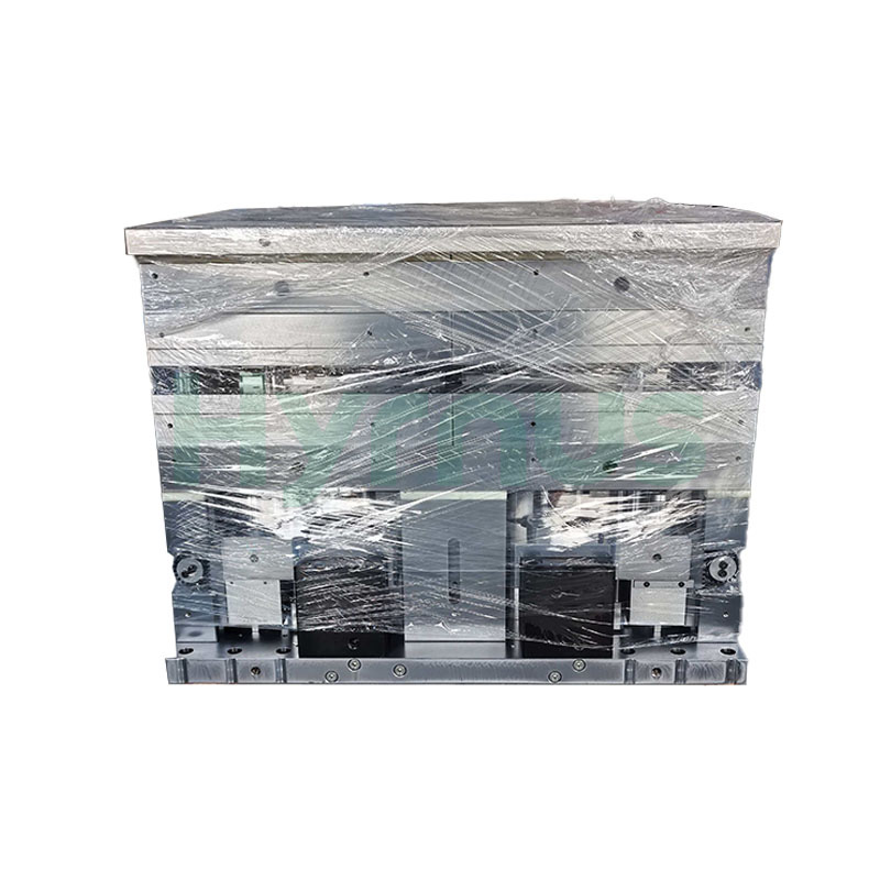
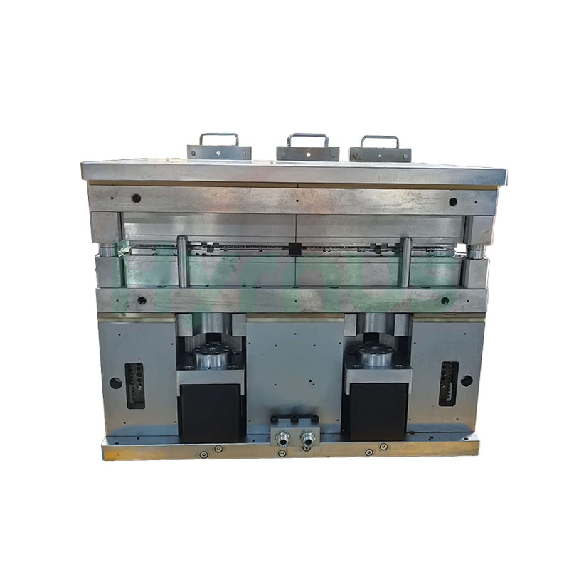
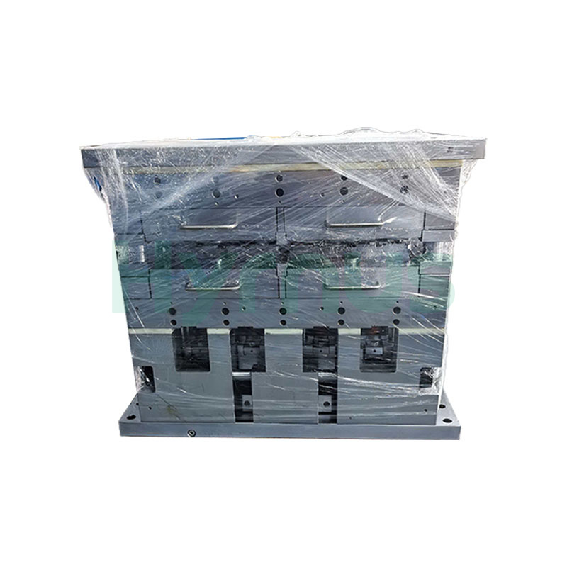
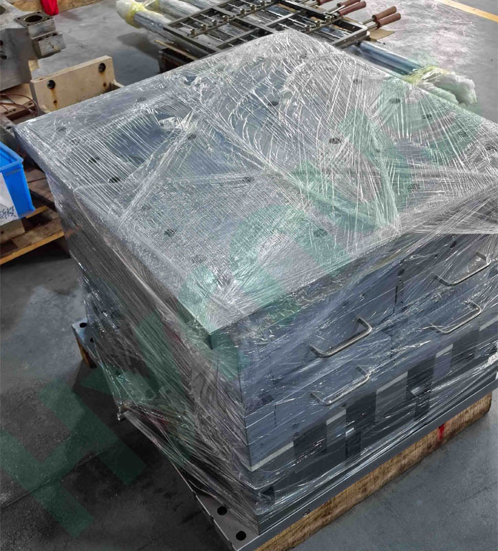
HY-PM23 MGP plastic molding die is customized for SOT23-20R semiconductor packaging. It is equipped with 6 mold boxes; each mold box holds 2 lead frames, with a total of 12 lead frames per full mold. All mold boxes and internal components are fully interchangeable and feature a quick disassembly and replacement structure.
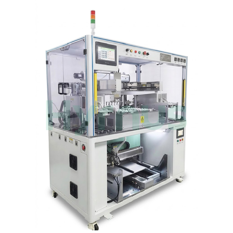
HY-AU400 is an integrated machine serving as professional auxiliary equipment for IC plastic molding molds. It realizes automatic lead frame preheating and molding compound pellet arrangement. Fitted with robotic arms and multi-point temperature control, it adapts to all IC packaging varieties, reduces manual contamination, lifts production efficiency, and supports optional MES system networking.

HY-MF300 is auxiliary equipment for plastic packaging molds, capable of one-time removing runner and gate residual flash for all IC packages. Equipped with Mitsubishi/Yonghong PLC control and full safety interlocks including light curtain, door sensor, E-stop and two-hand buttons, it delivers stable performance and universal compatibility for all semiconductor packaging production lines.
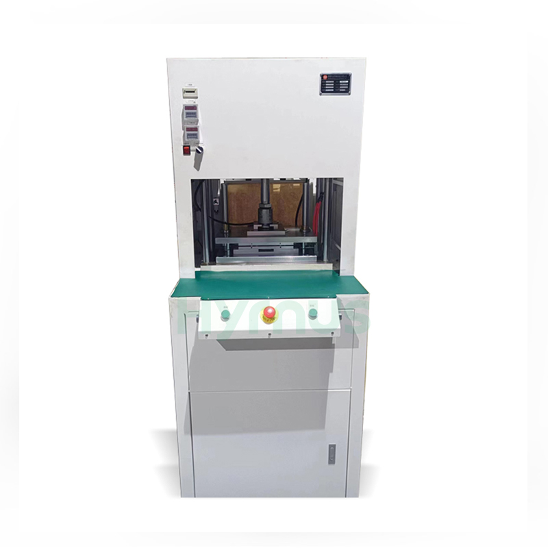
The HY-GD001/HY-GD803/HY-GD001A Automatic Degating Machine is designed for removing gates and runners from molded semiconductor leadframes. It combines precise punching, automatic air blowing and waste collection, while the mistake-proof mold and safety light curtain ensure reliable and safe operation.
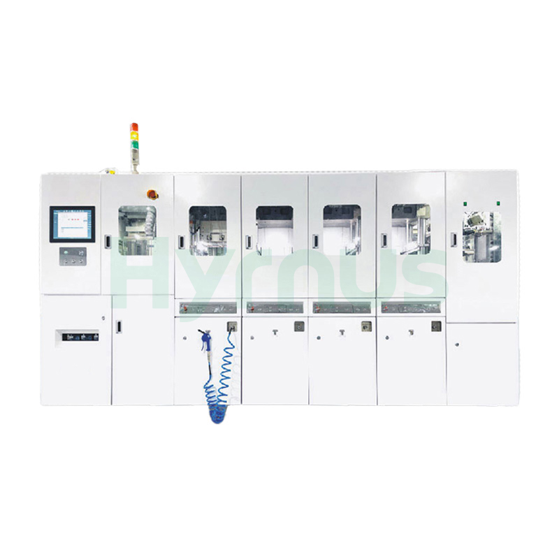
HY-PS8120 Molding System is a fully automatic molding system designed for semiconductor packaging, supporting a wide range of package types including SOT, SOP, TOLL, TO, QFN, DFN, and BGA.
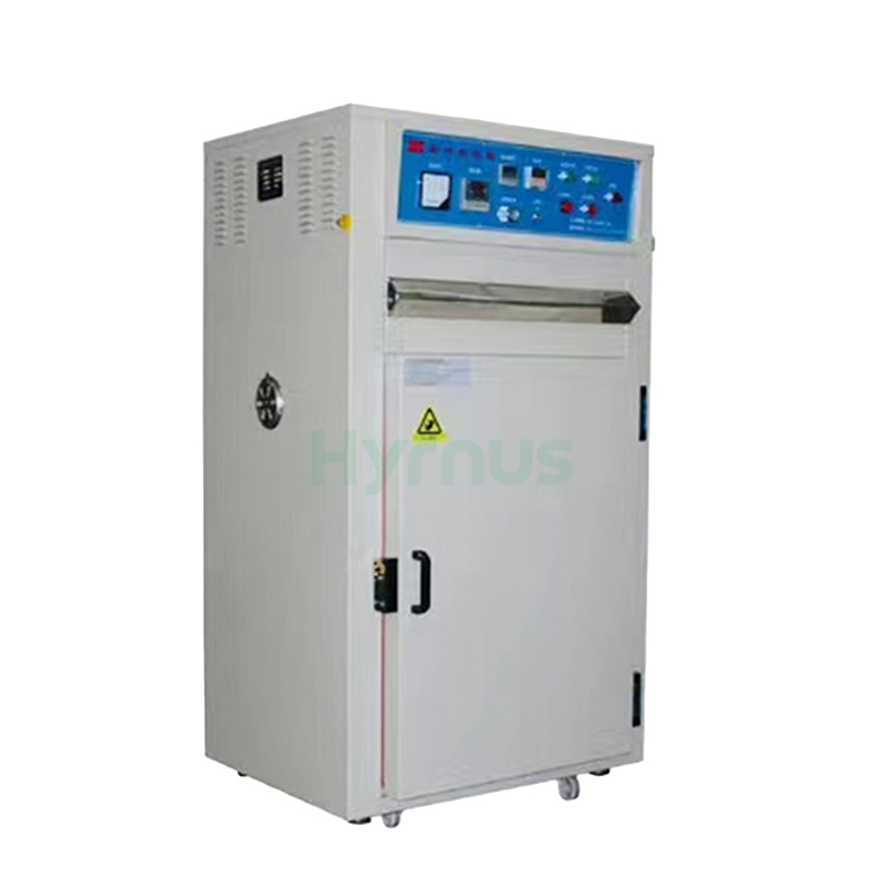
HY-LB200 Optoelectronic Drying Oven is designed for baking and drying electronic and hardware products at temperatures below 200°C. Equipped with PID temperature control, adjustable air circulation, timing settings, and multi-level over-temperature protection, it ensures stable and reliable operation. The stainless-steel chamber offers excellent durability and corrosion resistance, making the oven especially suitable for LED diodes, digital displays, backlights, and similar optoelectronic products.
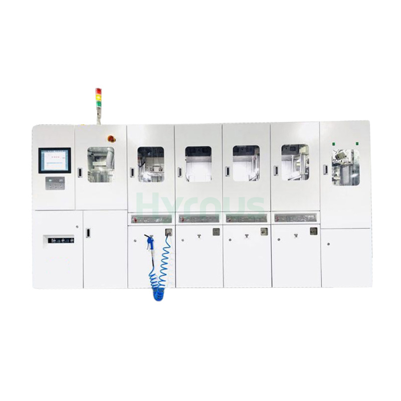
HY-PS8180 Fully Automatic Semiconductor Molding System is designed for efficient encapsulation of ICs and power devices, ensuring stable quality and reliable protection.
leave a message
Scan To Wechat :

Scan To WhatsApp :