
What Are You Looking For?

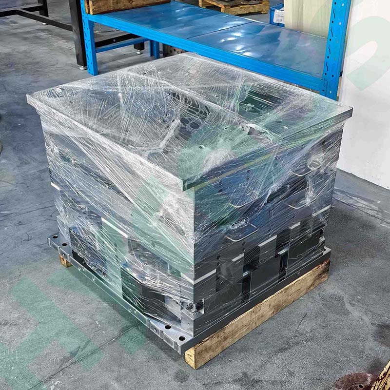
HY-PM220 is a TO220 MGP encapsulation mold featuring 320 cavities and 4 interchangeable mold cassettes, compatible with 450-ton and above molding presses. It adopts hard chrome plated cavities to maintain stable performance up to 100,000 shots, offering high-precision molding for semiconductor power device packaging with complete supporting spare parts.
Brand :
HYRNUSItem No. :
HY-PM220Order(MOQ) :
1 SetWarranty :
One-Year Warranty and Lifetime MaintenancePayment :
T/TLead Time :
7-35 DaysProduct Origin :
ChinaTO-220 320-Cavity MGP Encapsulation Mold

Product Introduction
HY-PM220 TO220 320-Cavity MGP Encapsulation Mold is a high-volume precision semiconductor packaging mold customized for TO220 power device epoxy molding processes. Each set contains 4 fully interchangeable mold cassettes, with 2 lead frames loaded per cassette; the whole mold can process 16 lead frames in a single molding cycle to reach 320 forming cavities in one shot. Designed with a bottom-up multi-pot injection system and quick-swap modular cassettes, this MGP mold fits all mainstream 450T+ semiconductor molding machines perfectly.
It addresses common drawbacks of conventional single-cavity molds including low production throughput, long mold replacement downtime and out-of-tolerance dimensional deviation. All indicators of dimensional accuracy, ejection smoothness and cavity coating performance remain consistent within 100,000 shots or 1 year of continuous service. It is widely used for encapsulation of TO220-packaged MOSFETs, power transistors and voltage regulators in mass production lines.
Product Application
HY-PM220 TO220 MGP encapsulation mold adopts a 320-cavity design for TO220 power discrete components such as MOSFETs, power transistors, LDO regulators and Schottky diodes. It serves semiconductor packaging factories, automotive electronics workshops, power supply and new energy manufacturers. Molded devices are applied in consumer adapters, vehicle power modules, industrial inverters, portable energy storage and portable medical equipment, and the mold is compatible with all fully automatic 450-ton and above molding production lines.
Quality Control & Acceptance Standard of MGP Molding Die
Below are full inspection standards for finished devices molded by HY-PM220 320-cavity TO220 MGP encapsulation mold, covering dimensional tolerance, flash control, molding parameters, surface & internal defects and long-term cavity coating durability for mass semiconductor packaging production.
All dimensions mentioned below are measured in mm unless otherwise specified.
1. Dimensional & position tolerance
All outline size, draft angle and lead thickness follow product drawings with hard chrome plated cavity. X/Y encapsulant offset and center offset between mold compound and lead frame shall not exceed 0.05.
2. Flash & residual compound control
Flash on runner, vent and gate shall not block automatic production. Protruding gate residue on frame edge is forbidden. Only transparent flash within 0.6mm is permitted on device pins.
3. Demolding & molding parameters
Smooth ejection without broken runners or culls, stable within 100,000 shots. Standard process: mold temp 160~180℃, injection pressure 1000~1600psi, cycle time 8~25s.
4. Surface defect limits
No scratches, wave marks, cracks or chipping on molded parts; bubble & pinhole size <0.1mm. Vertical flash at insert joint ≥0.05. Central cull overflow ≥0.05 (within 100,000 shots: thickness<0.05, width<2). Runner side overflow ≥0.05 (within 100,000 shots: thickness<0.05, width<1). No lead frame deformation or locating hole crack after demolding.
5. Internal encapsulation performance
Zero voids & delamination on die and bonding wire area; voids at other internal positions ≤0.1mm, incomplete filling is prohibited.
6. Cavity plating service life
Min. 100,000 shots for green compound, min. 200,000 shots for standard compound, no coating peeling during service cycle.
MGP Molding Die Configuration & Technical Specifications
This section shows the complete mold configuration standards of HY-PM220 TO220 MGP encapsulation mold, covering main mold body structure, thermal insulation accessories, electrical fittings, press matching parameters and material hardness requirements. All specifications are fully compliant with semiconductor power device mass production encapsulation standards for 450-ton and above molding presses.
Note: All dimensional units in the table are mm unless otherwise stated.
| No. | Category | Item | Technical Standard |
| 1 | Main Mold Body | Compatible Molding Press | The mold can be matched with molding presses of 450 tons or above; the mold frame is universal for 4 mold cassettes with quick cassette replacement design. |
| 2 | Main Mold Body | Injection Driving Mechanism | Bottom-to-top multi-cylinder injection design. Injection action is driven by built-in high-temperature leak-proof dual hydraulic cylinders, executed by the injection drive plate with balancer design. |
| 3 | Main Mold Body | Full Cassette Interchangeability | All cassettes are fully interchangeable on the frame, without fixed position identification requirements. |
| 4 | Main Mold Body | Internal Parts Interchangeability | All components inside each cassette are fully interchangeable for free replacement. |
| 5 | Main Mold Body | Quick Cassette Replacement Structure | The cassette adopts built-in ejector pin plate mechanical structure connected to the mold frame’s ejection drive device, with slide rail pull-in design to realize fast cassette replacement. |
| 6 | Main Mold Body | Core Component Material & Hardness | The mold cassette and key components adopt materials as follows: |
| ① Mold cassette: DC53 (hardness HRC59~60) | |||
| ② Cavity insert: ASP23 (hardness HRC61~63) | |||
| ③ Center block: ASP23 (hardness HRC61~63) | |||
| ④ Injection cylinder: ASP23 | |||
| ⑤ Injection tip: Tungsten steel | |||
| 7 | Main Mold Body | Lead Frame Loading Rack | The lead frame loading rack is made of high-strength aluminum alloy, lightweight and anti-deformation. The floating rack design ensures smooth feeding without interference. |
| 8 | Main Mold Body | Cavity Surface Roughness | The machined surface roughness of the cavity shall meet the requirements of molded product outline dimension drawing. |
| 9 | Main Mold Body | Multi-Zone Independent Temperature Control | Thermocouple holes are reserved beside each heater hole on upper and lower mold frames to match 24-point temperature control molding presses with independent temperature control for each heater. 4 thermocouple holes are reserved at the rear of upper and lower frames, compatible with molding presses with only 2 or 4-zone temperature measurement design. |
| 10 | Main Mold Body | Over-Temperature Cut-off Sensor Port | Over-temperature cut-off sensor mounting holes are reserved on upper and lower frames to cooperate with the over-temperature cut-off sensor equipped on the molding press. |
| 11 | Main Mold Body | Air Cushion Base Plate | The lower mold base plate adopts air cushion design for convenient mold installation. |
| 12 | Main Mold Body | Frame Fixing Structure | Upper and lower frames are fixed by L-shaped fixing plates to fit platforms of different molding presses. |
| 13 | Main Mold Body | Fastener Standard | All screws and nuts inside the mold adopt metric standard sizes. |
| 14 | Main Mold Body | Quick Injection Drive Connector | The connector fixing base and injection drive plate adopt slide rail sleeving, pulling and locking design. |
| 15 | Main Mold Body | Mold Surface Temperature Difference Control | The power of heating rods is selected to keep the temperature difference between upper and lower mold surfaces within ±5℃. |
| 16 | Main Mold Body | Heater Power Marking | Power marking must be printed at the root of each heating tube. |
| 17 | Main Mold Body | Heater Fixing Bracket | Heating tube fixing devices must be arranged around each heating tube hole of the mold. |
| 18 | Thermal Insulation Accessories | Thermal Insulation Jacket | Fixed thermal insulation jacket for upper mold; quick detachable insulation plates on both sides of lower mold. |
| 19 | Thermal Insulation Accessories | Heat Insulation Plate Performance | All mold insulation plates can withstand long-term clamping pressure impact without deformation and will not damage the mold surface. |
| 20 | Electrical & Clamp Fittings | Heater Parameter Marking | Marked with rated power and working voltage. |
| 21 | Electrical & Clamp Fittings | Thermocouple Interface | Matches buyer’s molding press, supports 2-point, 4-point and 24-point temperature control. |
| 22 | Electrical & Clamp Fittings | Thermal Protection Interface | Matches buyer’s molding press. |
| 23 | Electrical & Clamp Fittings | Pressure Plate Structure | Matches buyer’s molding press. |
| 24 | Electrical & Clamp Fittings | Upper & Lower Mold Plate Thickness | Plate thickness must be greater than 40mm. |
| 25 | Electrical & Clamp Fittings | Pressure Plate Fastening Mode | The pressure plate is tightly pressed on the mold plate. |
| 26 | Electrical & Clamp Fittings | Pressure Plate Screw Specification | Matches the molding press provided by the buyer. |
| 27 | Press Matching Parameters | Press Ejector Pin Layout | Ejector pin positions are selected according to actual mold structure. |
| 28 | Press Matching Parameters | Press Platen Size | Provided by the buyer. |
| 29 | Press Matching Parameters | Mold Air Float Interface | Matches standard air float interface of molding equipment. |
| 30 | Press Matching Parameters | Hydraulic Hose Connector | Matches hydraulic hose connector of the molding press. |
| 31 | Press Matching Parameters | Cavity Layout Drawing | Refer to molded product drawing. |
| 32 | Press Matching Parameters | Total Mold Thickness | The total mold thickness after mold closing is more than 520mm, manufactured in accordance with current mold design standards. |
Product Details
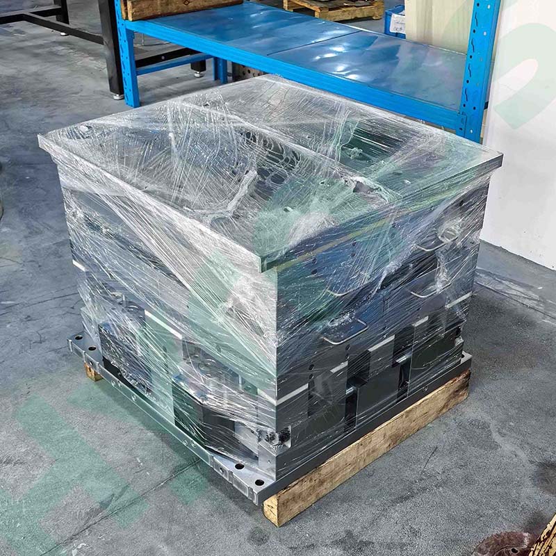
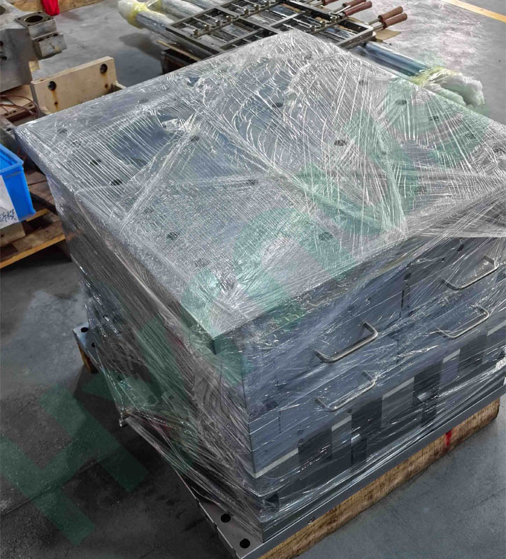
HY-PM23 MGP plastic molding die is customized for SOT23-20R semiconductor packaging. It is equipped with 6 mold boxes; each mold box holds 2 lead frames, with a total of 12 lead frames per full mold. All mold boxes and internal components are fully interchangeable and feature a quick disassembly and replacement structure.
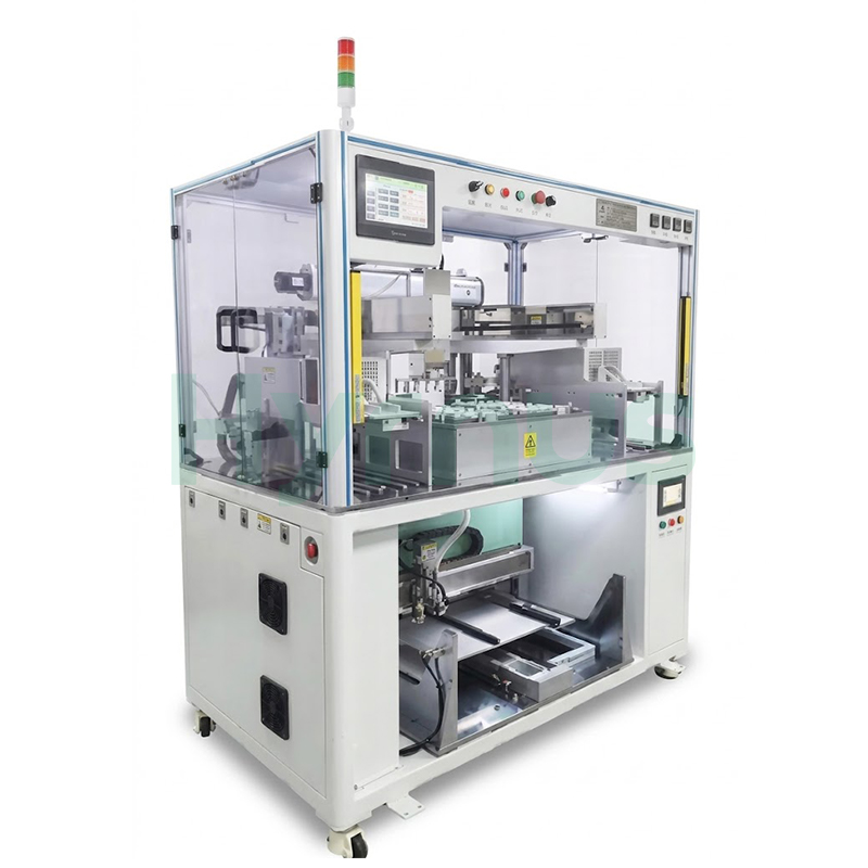
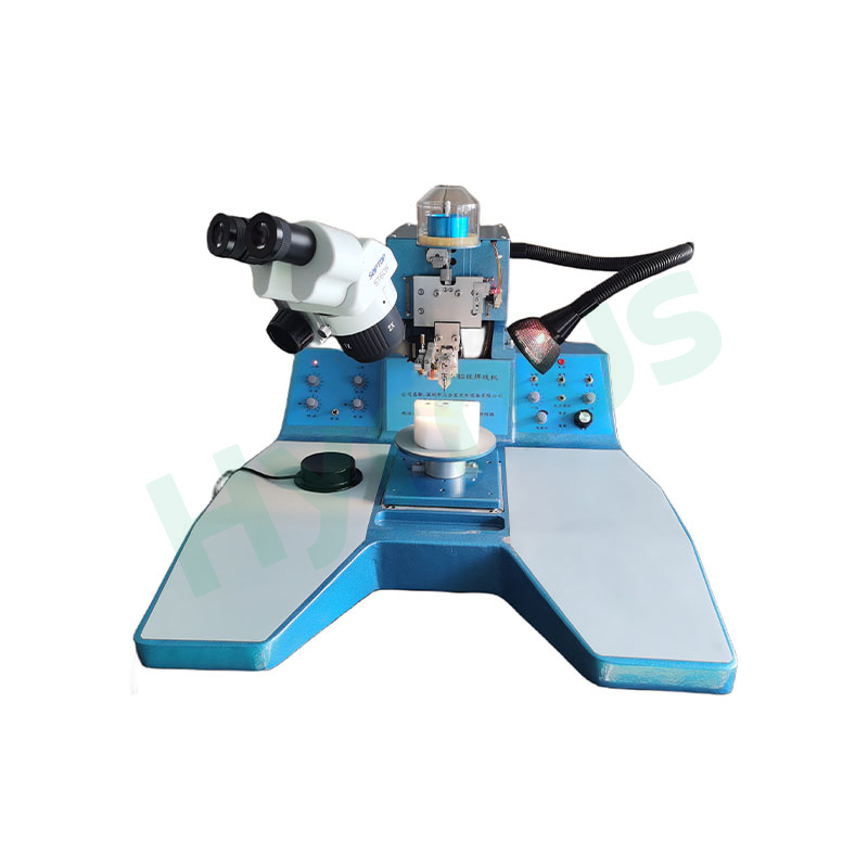
HY-AU400 is an integrated machine serving as professional auxiliary equipment for IC plastic molding molds. It realizes automatic lead frame preheating and molding compound pellet arrangement. Fitted with robotic arms and multi-point temperature control, it adapts to all IC packaging varieties, reduces manual contamination, lifts production efficiency, and supports optional MES system networking.

HY-MF300 is auxiliary equipment for plastic packaging molds, capable of one-time removing runner and gate residual flash for all IC packages. Equipped with Mitsubishi/Yonghong PLC control and full safety interlocks including light curtain, door sensor, E-stop and two-hand buttons, it delivers stable performance and universal compatibility for all semiconductor packaging production lines.
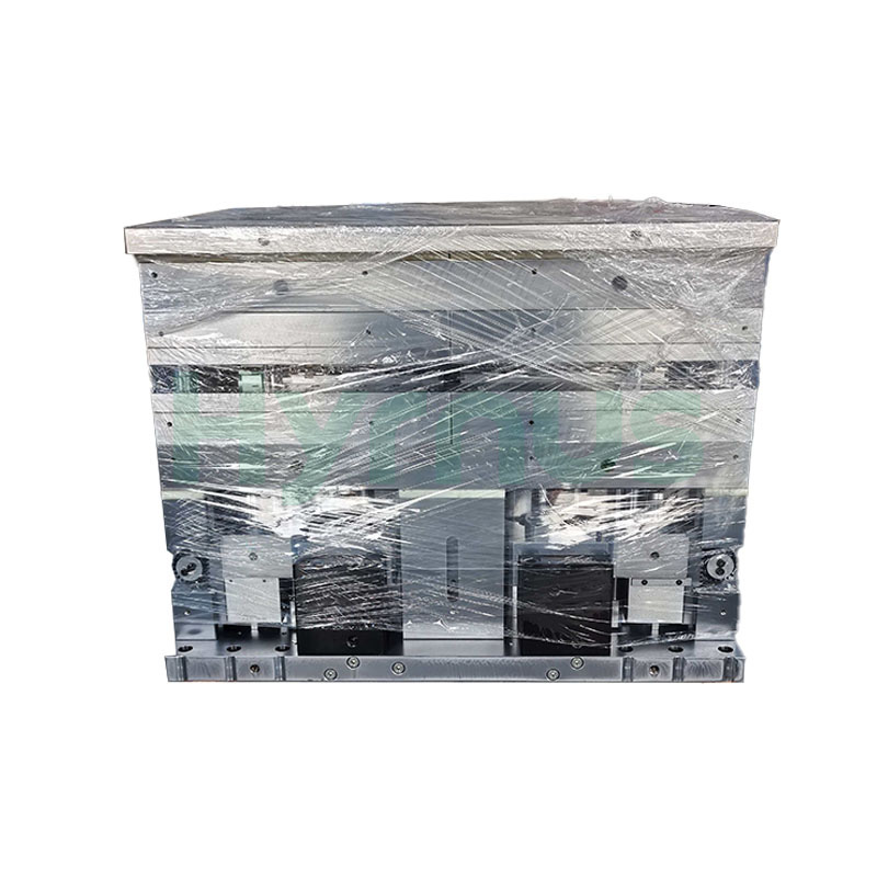
HY-PM252-6R Molding is a high-precision molding mold designed for TO252-6R package products. The mold features a universal mold base capable of accommodating 6 mold boxes with quick mold box change design, utilizing a bottom-to-top multi-pot injection design driven by four built-in high-temperature-resistant, leak-proof hydraulic cylinders with a balanced injection head drive plate.
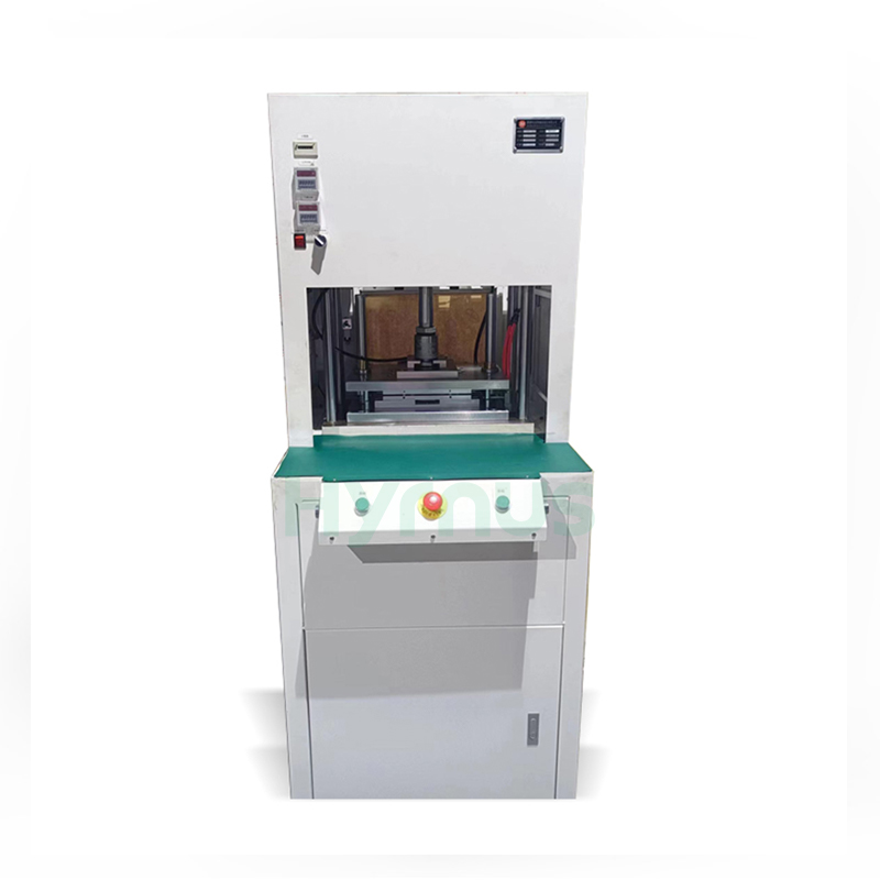
The HY-GD001/HY-GD803/HY-GD001A Automatic Degating Machine is designed for removing gates and runners from molded semiconductor leadframes. It combines precise punching, automatic air blowing and waste collection, while the mistake-proof mold and safety light curtain ensure reliable and safe operation.
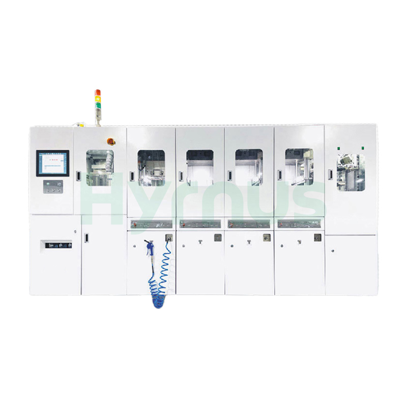
HY-PS8120 Molding System is a fully automatic molding system designed for semiconductor packaging, supporting a wide range of package types including SOT, SOP, TOLL, TO, QFN, DFN, and BGA.
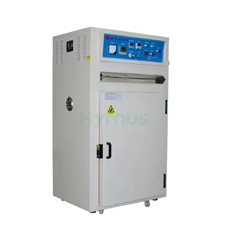
HY-LB200 Optoelectronic Drying Oven is designed for baking and drying electronic and hardware products at temperatures below 200°C. Equipped with PID temperature control, adjustable air circulation, timing settings, and multi-level over-temperature protection, it ensures stable and reliable operation. The stainless-steel chamber offers excellent durability and corrosion resistance, making the oven especially suitable for LED diodes, digital displays, backlights, and similar optoelectronic products.
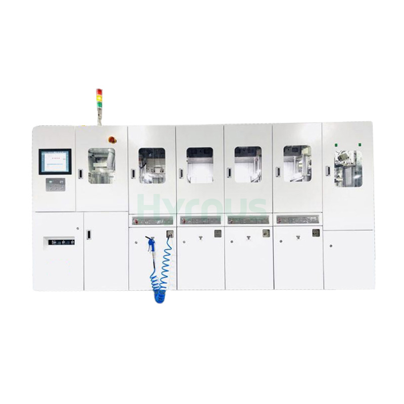
HY-PS8180 Fully Automatic Semiconductor Molding System is designed for efficient encapsulation of ICs and power devices, ensuring stable quality and reliable protection.
leave a message
Scan To Wechat :

Scan To WhatsApp :