

What Are You Looking For?
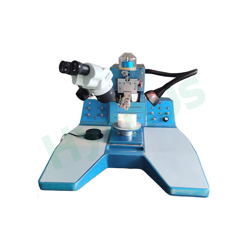

HY-DD560P is dedicated production equipment for COB and COC processes. It mainly performs epoxy dispensing and die bonding between substrates (PCB or other carrier materials to be processed) and chips. Integrated with automatic loading/unloading, parallel dispensing & die picking, and multi-CCD vision positioning compensation full-automatic workflow, it enables stable high-precision die attaching and bonding, suitable for mass packaging production of optoelectronic and communication chips.
Brand :
HYRNUSItem No. :
HY-DD560POrder(MOQ) :
1 SetWarranty :
One-Year Warranty and Lifetime MaintenancePayment :
T/TLead Time :
7-35 DaysProduct Origin :
ChinaAutomatic Epoxy Dispensing and Die Bonder for COB/COC Flip Chip Manufacturing

Product Introduction
HY-DD560P Automatic Epoxy Dispensing and Die Bonder is professional all-in-one machinery specially designed for COB and COC packaging workflows. Its core function is to finish epoxy dispensing and die bonding tasks between substrates (including PCBs and other processing carriers) and microchips.
This machine adopts a dual-cassette auto loading & unloading structure. Operators only need to manually place substrate trays into cassettes and load chip gel-paks or blue film wafers before automatic production. It is fitted with two dedicated robotic arms, one for dispensing and the other for die pickup, working simultaneously to shorten cycle time and boost throughput. A complete multi-CCD visual system enables full-process real-time position correction: CCD1 locates substrates, CCD2 calibrates chip front sides, and CCD4 provides secondary back-side alignment for precise bonding. Once one tray is fully processed, it returns to the cassette automatically and the machine proceeds to the next tray. When both cassettes finish processing, the system reminds operators to replace cassettes for non-stop mass production. It delivers stable high-precision die mounting and bonding, ideal for mass packaging production.
Component List
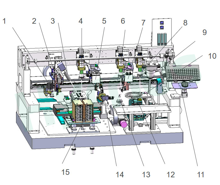
| No. | English Name |
| 1 | Glue dispenser tray |
| 2 | Dispensing manipulator |
| 3 | Monitoring camera |
| 4 | Substrate positioning CCD 1 |
| 5 | Die bonding manipulator |
| 6 | Die front alignment CCD 2 |
| 7 | Die pick-up manipulator |
| 8 | Die wafer CCD 3 |
| 9 | Microscope assembly |
| 10 | Die wafer (TRAY) assembly |
| 11 | Keyboard & mouse placement area |
| 12 | Ejector pin assembly |
| 13 | Die alignment stage |
| 14 | Die back alignment CCD 4 |
| 15 | Substrate fixture XY stage + magazine lifting system |
Working Principle & Process Flow
HY-DD560P is a production equipment used for bonding substrates (PCB or other materials to be processed) and dies through dispensing process in COB/COC manufacturing.
Manual Loading
1. Put the substrate trays into cassettes, then mount the cassettes onto the cassette lifting system.
2. Manually place chip gel-paks or blue film wafers.
Automatic Working Process
1. After startup, the cassette lifting mechanism moves up and down, and the substrate XY stage transports the substrate tray under CCD1. After image capture and recognition, the system feeds back data to realize position compensation for the substrate stage.
2. The dispensing robotic arm dips glue from the glue tray and moves above substrates for dispensing. Simultaneously, the die pick-up robotic arm picks chips from the wafer and places them on the lower nozzle of the calibration stage for front-side chip identification.
3. CCD2 performs identification, and the calibration stage compensates position deviations in XY and θ directions.
4. The die bonding robotic arm picks up calibrated chips, carries out secondary alignment compensation via back-side calibration CCD4, then moves to substrates to complete die attaching.
5. Once all chips on one tray are bonded, the tray is sent back to the cassette, and the machine processes the next tray.
6. When both cassettes finish all bonding tasks, the system prompts operators to replace empty cassettes to resume production.
Main Component Overview
| Component Name | Brief Introduction |
| 1. Robotic Arm & Dispensing Assembly | X/Y axes adopt linear motors, voice coil motors and 0.1μm linear scales, repeat accuracy ≤±0.5μm. Bakelite nozzles with 10–50g pressure range. Mature glue tray for stable dispensing volume. Equipped with dispensing arm, ±5° rotary bonding arm and 180° flip pick arm. |
| 2. Wafer & Tray Assembly | Built with 6-inch wafer ring, tray clamp, ejector pins and XY stage. Two chip separation modes: membrane pulling and pin lifting. |
| 3. Die Pick Nozzle Unit | XYZ 3-axis linkage with buffer, 20–50g mechanical pressure, flow detection for chip judgment. 180° flip structure to realize flip-chip packaging. |
| 4. Die Bonding Nozzle Unit | XYZ 3-axis linkage with buffer, adjustable pressure 10–50g and flow monitoring. Rotation unit completes back-side chip calibration via vision. |
| 5. Chip Calibration Stage | Xθ with GMT modules, Y axis with HIWIN modules for 3-axis movement. Calibrates chip front side and compensates substrate angle deviation based on vision data. |
| 6. Working Platform | Substrate XY stage uses linear motors and 0.1μm linear scales, repeat accuracy within ±0.5μm, matched with material clamping mechanism. |
| 7. Tray & Cassette Lifting System | Driven by stepping motors for vertical cassette movement. Cooperates with the stage clamping unit to realize automatic loading and unloading, greatly improving production efficiency. |
| 8. CCD Vision System | 3 sets of vision modules with industrial cameras, lenses and multi-type adjustable LED light sources. Includes front-side and back-side CCD for high-precision positioning. |
| 9. Dispensing Unit | Rotary glue tray with flat wiper to control dispensing volume by adjusting wiper thickness. Dispensing head installed on XYZ robotic arm for flexible position adjustment. |
Technical Specifications
| Item | Details |
| Equipment Dimensions | X1640 × Y1420 × Z1840 (mm) |
| Weight | 1500 KG |
| Power | 4 KW |
| Air Pressure | 0.4~0.6 MPa |
| Voltage | 220 V |
| Positioning Accuracy | ±2 µm |
| Angle Accuracy | ±0.01° |
| Die Bonding Force | 10~50 g |
| Wafer Size | 6" (tray 2"×2") |
| Substrate Stage Travel | X200 × Y200 mm |
| Chip Size | 0.2~2 mm |
Product Details
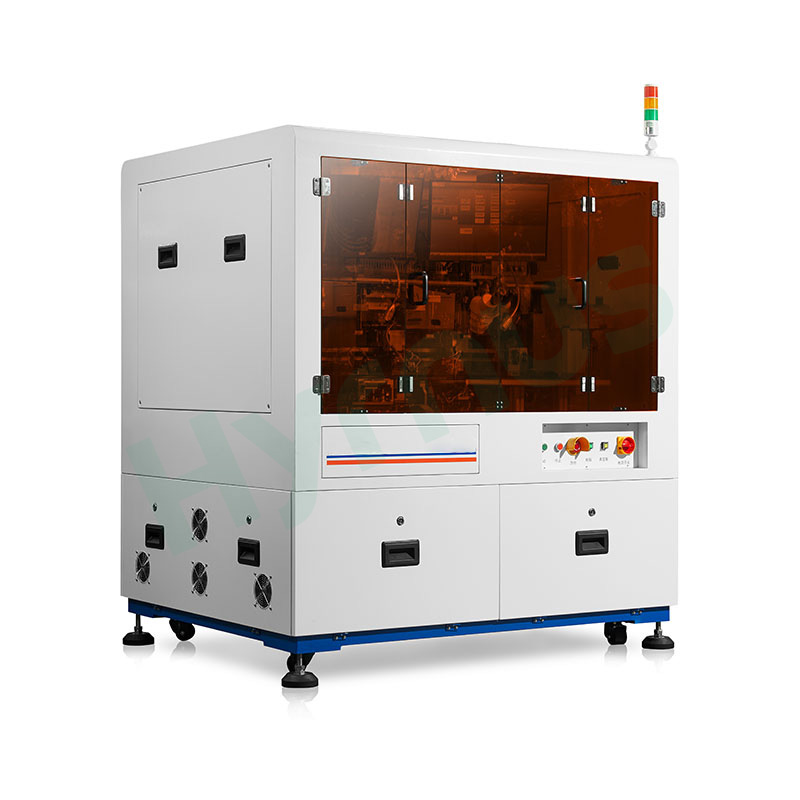
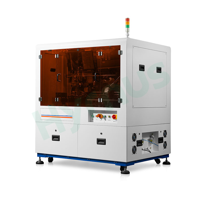
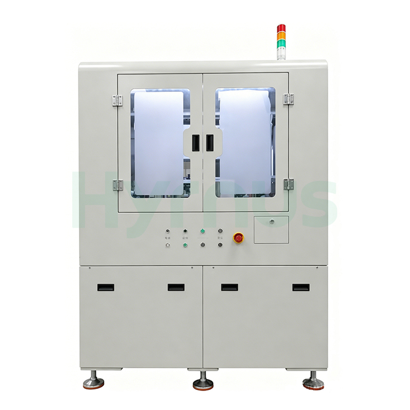
HY-ED022 Die Bonder is developed for Optical Communication and Optical Device Packaging applications.
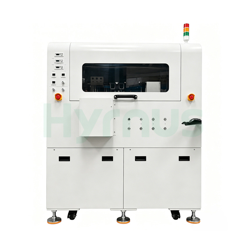
HY-ED010 Die Bonding Machine is a Die bonding machine developed for Automotive LED and Optoelectronic Semiconductor Packaging applications.
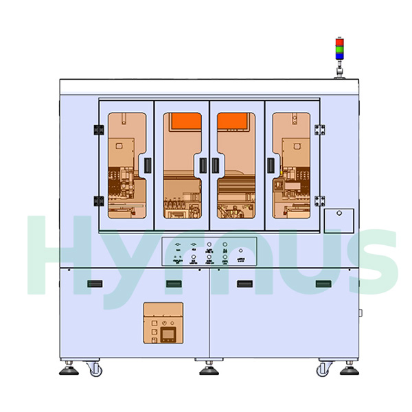
HY-ED007 Die Attach Machine is a High-Precision Die attach machine developed for Optical Communication, Optical Modules, Multi-Chip Modules (MCM), 3D Packaging, and Optoelectronic Device applications.
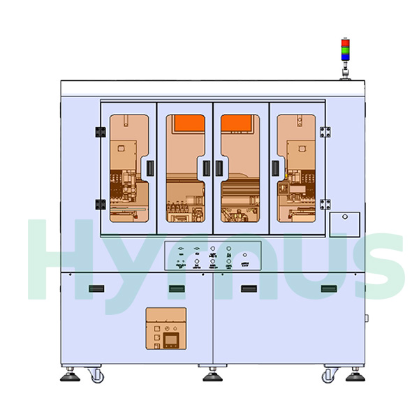
HY-ED003 Die Attach Equipment is a High-Precision Eutectic Bonder developed for Optical Communication, Optical Modules, Multi-Chip Modules (MCM), 3D Packaging, and Optoelectronic Device applications.
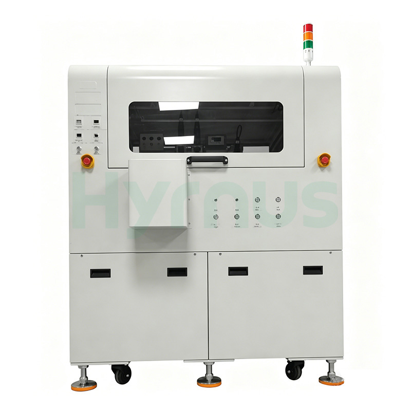
HY-DB504 Die Bonder is a Fully Automatic Die Bonder developed for Ultra-High-Precision Optoelectronic and Semiconductor Packaging applications.
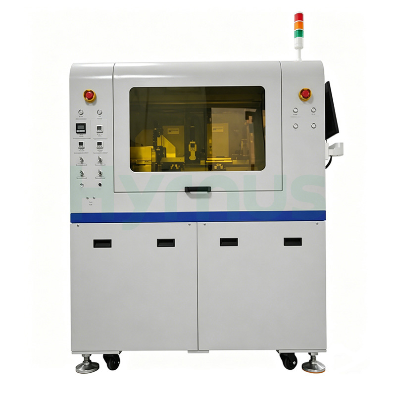
HY-DB503 Die Bonder is a High-Speed Fully Automatic Die Bonder developed for Optoelectronic and Semiconductor Packaging applications.
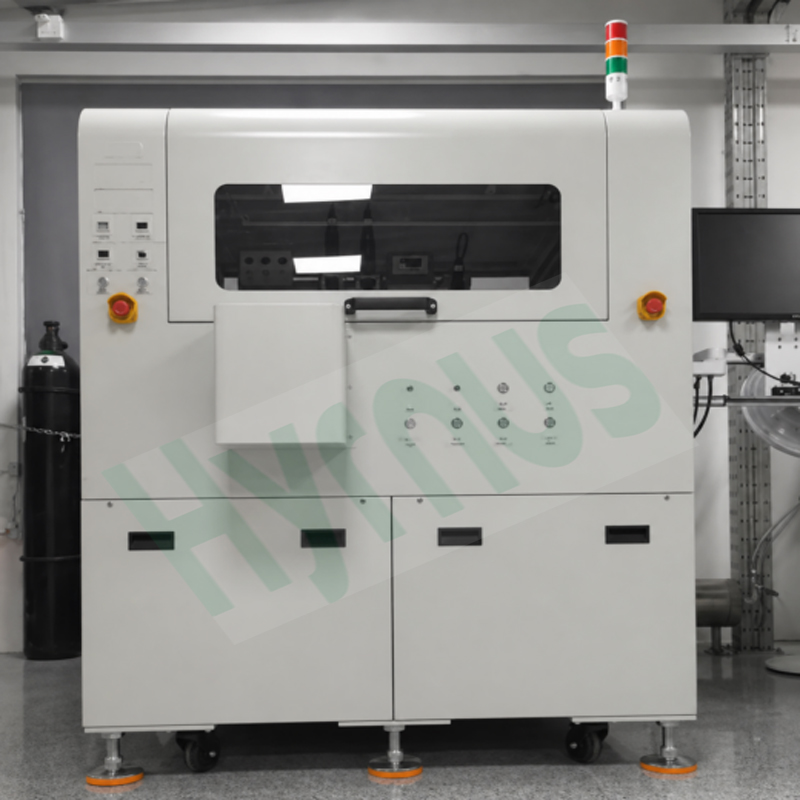
HY-DB501 Die Bonder is a fully automatic die bonder developed for ultra-high-precision optoelectronic and semiconductor packaging applications.It delivers precision-driven die attachment for optoelectronic packaging, targeting TO‑series devices, photodiodes, lasers, optocouplers, and miniLEDs with placement accuracy of ±5 μm and angular control within ±1°.
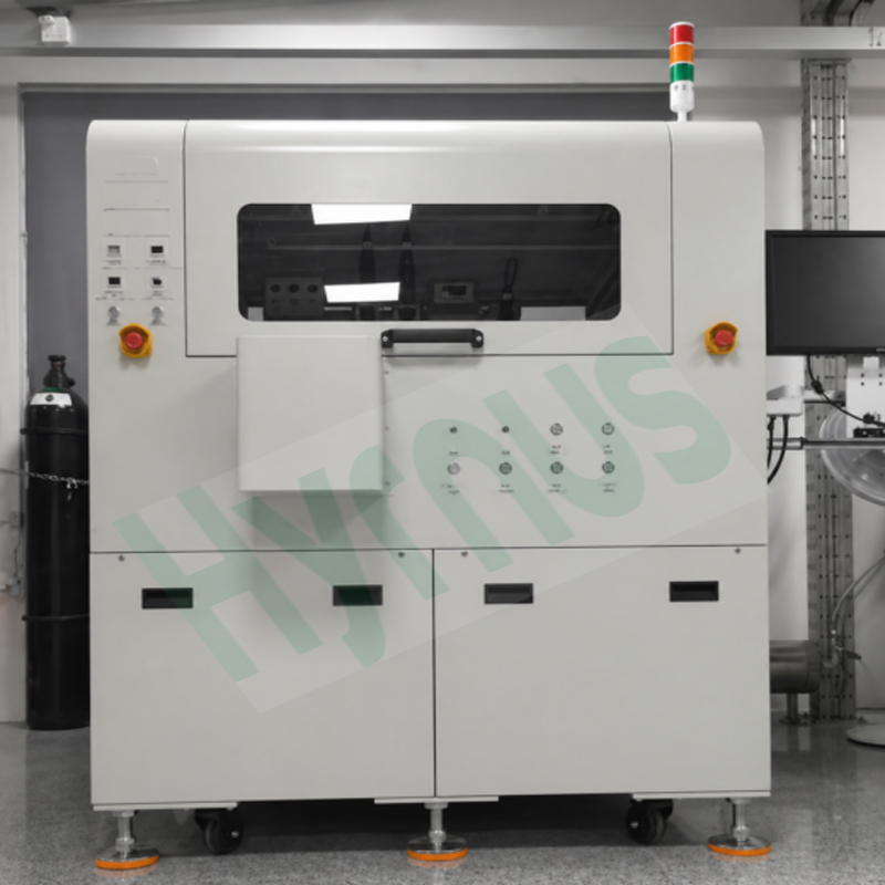
HY-DB500 Die Bonder is a high-end, fully automatic die bonder engineered for optoelectronic devices and high-precision semiconductor packaging. Built with exceptional stability, intelligent control, and a modular architecture, it is ideally suited for high-volume production of TO-series devices, photodiodes, lasers, optocouplers, miniLEDs, and consumer optoelectronic components.
leave a message
Scan To Wechat :

Scan To WhatsApp :